Friday, September 30, 2011

Aikido Pre-amp Project - Part 6

We have bulldozed this far where we had enough numbers & design plans to start building.

Arfter simmering the whole battle plan for a few day; Lets give it a trim.
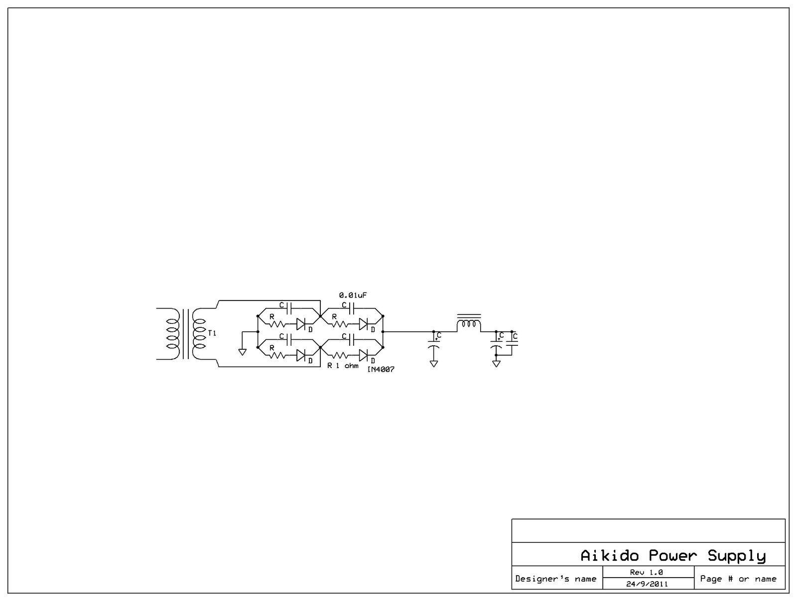
PSU Sanity Check

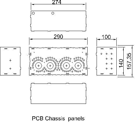
Since I decided on a PCB, I'll just let it free from hacking for now, that leasves only the PSU to comfort my bloated ego...

For the choke, a snubber is added for taming stray capacitance of the choke, also a diode for safety.
This bridge ractifier is build from discrete parts, & the actual parts connections are as shown in the following drawing.
All is rosy until I realised this is too much work for a 12 year old....
So I drop the idea & use a package bridge ratifier instead. BUT there are no free lunch....
We gotta do something about the SS diode switching spike which will back feed into the main transformer secondary coil, induce noise in the primary & this will pass on to the other tranny connected to the same main.

The CLC filter which will not do anything to better the situation, it has to handle at the AC state.

An easier cocktail concoction fix.... Use fast recovery bridge for least switching spikes & connect a small value capacitor across the AC terminals on the Bridge rectifier  to tame the naughty spikes, not ideal, but that should get the job done...

No PCB require, the circuit is simple enough for wiring the component point to point.
 

Wait-up !!!

Tube will not conduct instantly from start up, they will only conduct when heated sufficiently by the filament. Unlike a tube ractifier, our solid state ractifier will not wait for that to happen. This instant high voltage will stress the tube & components. The risk is very especially pronounce with direct coupling circuit, which Aikido is. The consequence is premature death of the tubes concerned or fire..... which is a bad bad thing...

Capacitor Multiplier, A.K.A Gyrator 

The conventional wisdom is to throw in a timer delay relay circuit to facilitate time for the heater to raise the tube temperature. This calls for extra components, relays, another power supply for the circuit, breadboarding on perforated board or even making another PCB... Hack, I'm loosing hair just to come up with excuses for not doing it!!!

I'll go without any relays by implement a capacitor multiplier instead. As the name implies, its will mimic  huge physical capacitor of your choice value with 1 transistor, 2 resistor & 1 capacitor.

Like a real capacitor, it is very good at reducing ripples (High PSRR). It is not a voltage regulator as it will track the raw voltage & floats on the B+. AND it can reduce the power supply impedance to a single digit which is desirable

All are rosy..... BUT not what I'm after. I am after its 6dB/octave voltage built-up feature. Others are just mare bonuses... 


 MOSFET is the Chosen One!

BJT requires to pass at least 1ma to the gate, that will limit the size of the R value which make up the RC network ( the 500K & 68uF ) without eating up voltage; MOSFET on the other hand just need to see voltage at the gate without drawing any current, this gives a free hand to the resistor size selection.

Even though MOSFET will need to drop 4V to work, but really, loosing 4V on B+ really isn't an issue here.


Component sellection isn't critical.
Even though the potential across the MOSFET is only a few volts since it is actually floating on the B+. Being SS, they will let out the magic smove if hit by high voltage. Using one with at least the B+ voltage rating is a safe bet. Hence a IRF820 with 500V, 1.2A rating. which I happened to have in my hoard pile.
The 1K resistor acts as the grid stopper of IRF820.
The product of 500k resistor & the 68uF RC network gives time constant of 34 seconds. Since it is a 1st order network,  B+ will ramp up to 63%(~189V) in 34seconds. 102 seconds to get to 95% (285V), & nearly 3 minute to get to full B+. Plenty of lead time for the tube to heat up.

That should get the job done...

 Let Go Upstream...

Parasitic noise in the mains can stir up a havoc if not kept in checked... Not only we must stop these nasty noise from getting into our equipment. It is even more important to prevent the noise generated in our equipments from getting into the mains & contaminate other equipment sharing the same mains. They usually comes as common mode noise. What it means in layman terms is it is indescrimal & will superimpose themselves on any form of signals.

To reject common mode noise, we can make ourselves some(obviously) common mode filter.
 
You can make one with ease.

*PS,
Bi-filler wire means 2 wires side by side.
Drum Roll, Please....
Throw in the gyrator, snubbers, filament tranny, 0.1A slow blow fuse, a rocker switch, the IEC socket...  & he we have a family portrait.


This ought to do it....


>>>>Part 7 Preview<<<<

Your guess is as good as mine....

Wednesday, September 28, 2011

Aikido Pre-Amp Project - Part 5

Some definitions to put thing straight before we proceed further.

~"Cabinet"~
Enclosure use to barricade dangerous/fragile thingy from the public brutality.
It can be a plain container of any shape & material or
with lots of cosmatic & decor for aesthetic reason.
It may be water tight. air tight or fire proof depends on requirements.
Your imagination (or your budget...) is the limit...

~ "Chassis" ~
A structural platform from which we build stuff on. Be it a electrical & electronics appliance or a car. Others prefer to call it skeleton.
material is function & budget dependent...

Public Appearance

Lets examine the "genaric" form the modern Hifi tube-amp use.


Exposed Tubes with a couple of hundrad volt waiting for a good kill.


Anti-Children protection


same mo, same mo...


I highly suspect that cost cutting is at work...

That in my opinion is cheating... anything which has over 50V & conduct 100mA must be properly barricaded from fingers...


~Ye-Olde .....

In the early days of electronics.


Beautifully crafted cabinet encapsulate all high voltage stuff...


This was how they did it once upon a time.


The modern tube guitar amp took up the tradition.....


How I would go about this????


I like these form...


My experience says, stay away from metal works on cosmetic finishing, the cost for the setting up the right gear for high quality consumer grade finishing is not what typical DIY builders would like to put up with.

Wood on the other hand is manageable. The only catch is you gotta commit to generous use of elbow grease for lots of sanding, rubbing & polishing.

Woodpunk Aikido Preamp Cabinet.


This is my preliminary Woodpunk style cabinet.

This cabinet is for 3 chassis. namely, the PSU, PCB & a future DAC chassis.

I tried to keep the valves at least 75mm from any wood. Also, plenty of opening for warm air to escape to prevent localised heating & hence fire in the house.
Instead of using fabric, I will carve as many fretwork possible for ventilation & serve as a art decor... the openings should large enough for unrestricted air flow & small enough to keep itchy fingers at bay. The fretwork should be space strong enough to resist destructive+itchy fingers.

The front panel is finger joint to the bottom.

The back panel does not cover the whole rear end, instead, it leaves a 100mm opening for accessing to the rear end of the chassis. This is good for both fiddling with interconnect & plenty of x-section area for ventilation. The added advantage are added protection to your interconnection cable plug & you can't throw a stone & hit the valves directly :)

3 access opening on the bottem panel for accessing to the chassis separately. This will preserve the structural integrity of the bottom panel and having smaller chassis bottom cover which are easy to handle.

The top, sides, back panel are finger joint together to from a U cover which is detachable. The cover will have sliding grooves on the side panels which can slid into the front penal in the vertical direction. 


Choice of wood.... hmmmm... teak is my favorite but they are hard to come by these day, lets keep the selection open for the moment.

Will finish the wood in satin so as to show case the natural wood grain.


IMHO, this has the retro appearance & modern interior...

We have finally come to a solid visual of the finish project.

I'm done for this session....

....Part 6 Preview....

I haven't a clue....


Tuesday, September 27, 2011

Aikido Pre-Amp Project - Part 4

Works continue on chassis design...

We will take up where we left in part 3 where we gone as far as determining the required chassis dimension of such,
PCB chassis dimension :141 x 293 x 100mm (H)
                                         ~5-1/2" x 11-1/2" x 4" (H)
PSU chassis dimension : 121 x 293 x 100mm (H)
                                         ~4-3/4" x 11-1/2" x 4" (H)
Aluminium is the material of choice.

Determine Type of Chassis & its Construction Method
Nothing in my junk pile match the sizes required, not even aluminium metal containers or kitchen utensil which I can improvise.... :(

Instead, I found some 300 x 500 x 2mm thk aluminium sheets which sits on a shelve all by themselves.. These will be suitable for folding a chassis per sheet with some tweaks in the chassis dimension.
Before any further a do, I need details of the press brake that will be folding these chassis for further number twitching in the previous development drawings. A disappointing trip to my friendly neighbourhood sheet metal fabricator reviews that the smallest bending radius is 9mm which is IMHO too coarse for folding chassis with a million-dollar-look

 "Desperation is the mother of innovation"


More stock check on what are at my disposal, with a pinch of copy cat & a whole load of cheating... The following drawings appear progressively...


Don't know how you will coin it. Borrowed from wood joinery technique; Its basically a 3D jigsaw puzzle with tabs & tab holes.  Tabs & tab holes are employed for locating the panels in relation to each other accurately. They will be spot welded at the tab joints to ensure good electrical & rigid structural bonding.

While I was at it, conveniently added some perforation on the PCB chassis top panel to facilitate ventilation path while preserving the rigidity of the penal. No opening on the side panel as I'm too tired to do so...

Keen eye readers will notice by now that both PSU & PCB chassis are identical in size.

So, I cheated... .Uniformity is the current excuse of choice for my laziness... I am sticking to it.. :)

After burning more man hours on touching up the design with further detailing such as optimising material utilisation; The nested penal layouts were born.


I reckon this will be the eventual construction drawing... but I do expect "unforeseen" circumstances.

The next on the list is to put the design aside to simmer for a couple of days (maybe weeks) while I can go on with my day job. We will know if there are any need for further tweaking by then...

Before I switch off the PC, here are the summery,

~Dimensions~
External : 140(W) x 290(L) x 100mm(H)
                  ~5-1/2" x 11-3/8" x 3-15/16"
Internal  : 124(w) x 274(l) x 98mm(h)
                  ~4-7/8" x 10-25/32" x 3-7/8"

~Panel material~
2mm thick Alum Plate which is approximately 14Gauge.

~Construction method~
CNC machined panels with tabs & tab hole, held together by TIG spot weld.

~Finishing~
Wire brushed, with natural colour Anodised.


Another 10 man hour burnt....


Now I can stop staring at the monitor & rest....


...........PART 5 PREVIEW...........

It will be physical! 


Monday, September 26, 2011

Aikido Pre-Amp Project - Part 3

In the previous article, I've came to the following layout.
Commercial amplifiers does has similar form dimension, I will use Pioneer A400  foot print which is 16 1/2" x 12" (420x305mm) as a rough guide.
Layout is not strictly a 2D affair, in the real world, we have 3-dimensions to play with. We can stack irons on each other if I have a magnetic shield between them hence, I'll place the filament transformer under the aluminium plate & have the choke directly above of it without adverse effects.

That leads to Ver.2
We get a huge space at the bottom left corner, plenty of real estate for future additions.

It struck me that if we put the PCB & all the iron is 2 different casing & we get separate PSU arrangement!

 But I don't fell comfortable with that huge void in the PCB casing so one thing lead to another, another layout appears...


Here are the other views
  
I go for a 100mm height chassis for now but 80mm will be the bare minimum for any reasonable working space within the chassis.

All these work just to  obtain the dimensions require for chassis preparation, be it off the shelf or custom made. Do you feel why I always end up with chassis-less amp???  LOL!!!


I started with all the intention to produce a 3D model of the chassis, unfortunately, getting to this stage has eaten up over 24 man hours. Since I've got all the dimension required to start construction,  I'll have to take a short cut & skip the whole 3D modeling exercise... :(


A description of the 3D chassis instead... :(

PSU Chassis
The mains tranny and the filament tranny will be on top of the PSU chassis & the choke under the filament tranny separated by the chassis top panel. They are space up lavishly.

The void between the two are filled by the filtering circuit component within the casing.

The IEC socket will be on the back panel  since all commercial amps has the
On/Off switch on the front panel, I'll follow suit even though I feel like an idiot routing the wire loop from back to front & back again... also... I can use relay & implement remote activation but I don't have one in my junk pile... Lets just keep it simple...

PCB Chassis
The PCB mounted on the bottom of the top panel to keep them away from dust & most importantly exposure to any form of interference.
The tubes protrude through the 4 holes on the top panel for best possible ventilation. I choose to have the tube orientated as such for it is farthest possible from the PSU exposed irons.
Filament wire layout can make or break any tube circuit... they are very high on my priority list. Tug into the chassis corners & away from any signal wire, even if you have to detour. The twisted wire will be travelling along the bottom of the chassis as shown & go vertically into the +H & -H terminals on the PCB.
The signal in & out terminals are on the back panel as shown... Detailing the hole dimension will have to wait... 
The selector & volume pot will be located just beside the signal input terminals at the back panel. they are linked to the front panel via separate connecting rods. This is important as the raw input signal is weak, susceptible to noise corruption. The extra wire length will act as antenna to invite noise. For extra protection, tug the wire into the top corner (top & side panel).

Finally! We come to the point where there are enough numbers to proceed with chassis preparation.
Go find ready made chassis of in close proximity of 142x293x100mm & 120x293x100mm & start drilling.
OR

Fabicate from these developement drawings.


WATCH THIS SPACE!!!

Sunday, September 25, 2011

Aikido Pre-Amp Project - Part 2

In this post I'll go about the chassis layout.
This is going to be boring.... but its absolutely crucial for one to get this right before any physical work...

Again, I would lay down the requirement for this session
1) Safety
2) Hum free
3) Easy construction
4) Good ventilation

Start the crunch....

A well laid chassis will keep noise & hum from bothering our sanity, prolong equipment life & safeguard any user from electrocution.
Hum & noise, a part from destructing for our sanity, they will definitely corrupt the signal we wish to process. The most significant effect of corrupted signal is noticeable loss in micro details, in a bad case, a blur broadcast with a constant hummmmmmmm...
A good electronic circuit is one which will reject unwanted signal while going about their intended purpose...
Weak signals are easily influence/corrupted by unwanted signal. such as RFI, EMI...etc. hence we must keep them away from noisy stuff such as EMI (electromagnetic interference) which are mostly generated by electromagnetic stuff such as electric motors, transformers, chokes, magnets...etc. RFI (Radio frequency interference) are generated by high frequency switches, PWM devices, radio wave transmission, microwave oven, solar burst... etc etc..
We can just shield external noise with a Faraday's cage which is basically putting everything inside a grounded non-magnetic metal chasing such as aluminium casing. Steel casing is ok but it does conduct magnetic thingy (which can be a PITA to debug) within the steel sheet unlike aluminium.
That take cares of the external noise. How about there are those internally generated noises within an amplifier.
General good practices in setting out an amp's interior layout is simply to separate the noisy stuff from the quiet stuff with air space. From my experience, most EMI can be minimised by a clear space of  50~65mm. To do this it is a good practice to make sure all the irons are amply spaced up with their coils perpendicular from each other & away from any signal path. Another good practice is to keep all the dirty & noisy stuff in one end & all the signal path in the furthest corner.The noisy stuff being anything closer to the mains supply & the quiet stuff are those closest to the signal inlet socket.
 
High current AC stuff induce electromagnetic field around them, disregard of their voltage.  Filament wire is one of the know culprit. There are many solution to this, one of which is to employ DC heater supply as DC current  induce very little electromagnetic field. That is the main reason for phono amps. DC filament supply can be complex & it has great impact on the sonic, particularly the size of the filter capacitor, it won't filter properly when its too small, & dull/death sound when you overdose... Some of the reader will enjoy tweaking the DC filament circuit but for me it is a PITA. 

It is no secret that I personally prefer AC heated tubes; IMHO, it is easier to build a fantastic AC heater filament implementation then to do a lousy DC filament implementation. Most importantly the lively & unstrained sonic energy it radiates. 

The simple solution to this is to use twisted filament wire, tug them into chassis corner, & keep them away from signal path. If crossing signal path is unavoidable, cross them perpendicular to each other. Less for more :)

Ground loop
Ground loop is the main culprit to hum... The practical approach of ground loop management is a faculty by itself  hence  not going to talk much of it. As for this build, I'll just take thing easy & go with the flow....

The Aikido PCB has a good star-ground layout, hence I'll use star ground scheme to manage the ground loop.

Transformers layout
It is necessary to finalise the PSU component selection before going about the irons placement in the chassis.
We need the PSU specs. before we can start & these are the numbers needed:-
Current requirement :  7.2ma x4= 28.8ma call it 30ma for convenient sake.
Voltage requirement : Since Aikido is not picky with B+ value, I'll just use what ever 230Vac, 50Hz can give which should fall anywhere between 300 & 325Vdc
Components I have : 8H @ 164 DCR Choke,  10uf, 68uf, 100uf, 120uf, 150uf, 220uf capacitor all rated at 450Vdc
Get PSUII out & play around with different parameters... Finally satisfy with the  following concoction...

from here, supplementing  other good design considerations & good DIY practices. An exact scaled 2D dimensioned chassis layout appears.


Well.... that goes another good 10 hours on the project  :)

As you can see, when one take all good practices into design considerations, there is no way a tube amp will get anywhere close to the size of 20 iPod stack.


.....Part 3 Preview.......

Churn out a 3D chassis design base on the 2D plan we had just cooked up...

Saturday, September 24, 2011

Aikido Pre-Amp Project - Part 1

Looking back my DIY audio journey, my objective in every project undertaking is to get to the point where a safe & functional good sounding amp soonest. My effort in aesthetic are limited to point-to-point circuit construction which is  beauty to my eye... There is just not enough energy left for aesthetic works....

This time round I'll will emphasise on the aesthetic work...But within reasonable degree of form-follow-function.

Like any projects in life, embarking on a project without laying down the goals is a sin...
Hence, a list of objectives in the order of priority
1) Quality finishing & Aesthetically appealing. Good enough to go on a display shelve.
2) All components must be from my junk pile.
3) Class II electrical safety compliance (double insulated form user)
4) Complete the project within 80 man hours
5) A project even a 12year old can complete.

Now the path is laid, one can start to eat the elephant a bite at a time...

DECISIONS, DECISIONS, DECISIONS...
Designing from scratch is fun but you are committed to a total unknown out come... Hence, this time, one gotta let go for one's ego for the better & use a trial & proven circuit.

Amplifier Design
A quick summary on Aikido. It is created by John Broskie. Requires 4 triode per channel to work, & the common practice is to use dual triode envelope valve, such as 12AX7, ECC88, 6N1P, ECC81, 6SN7... etc etc.
Aikido is such that it is almost immune to whatever tube selection or operating point (within common sense limits of course), it will produce fantastic audio result disregard. The only decision you will have to make is what sort of gain you need & what sort of output impedance you require... Spooky... :) To cut all the theory, I'll just say distortion cancellation is at work in this design...
Also, this amp is death quiet! It also design for power supply ripple cancellation!


I had built a myriad of Aikido pre-amps even using it as the driving stage of my 2A3 SE DHT with various tubes combinations & operation conditions; Construct using point-to-point construction technique, some uses bus bar ground & some using ground plane.

Sonic quality is fantastic, the image actually defy physical boundary & literally extends outside of the room! Neutral, dynamic & great micro-details are really high on the top echelon equipments.


Form of Construction
This is a solid design. Unfortunately, collect all the parts & construction from scratch will eat up the 80 man hour budget... even cutting my own PCB is out of the question...

I bought a few kits in return for John Broskie's generously sharing his work freely. This will be the best time to put them to their intended purpose.

This will be the second kit I build since I took the DIY path, the other kit was my inaugurate tube project which is a 6EW7 Kit from audiohobbyist many winters ago... And you guess right, the 6EW7 didn't survive my relentless hacking & eventually fell into pieces... Hope this Aikido will have better luck...

Tube Choice
6SN7 is the tube of choice, it can yield a gain near 10 &amp & when running this circuit at 300V & 7.2mA per tube we can have a super low Zo of 685ohm; Its perfect for a line stage & even also an great headphone amp!

Power  Supply Considerations
The kit has all the bells & whistles but you gotta build your own power supply.
6SN7 will work safely with 250V on the anode & when stacking 2 6SN7 it can safely use 500V B+ but since I have a few isolation transformers lying around, it will by default using B+ of 300~325V. Aikido is designed to have superb PSRR by design, but it helps with a solid & well filtered power supply.
I'll use the following power supply topology which I got repeated good results in the past. It sounds really close to a tube rectifier power supply.


That concludes the first 2 hour of work on this project.

Next 2 hours is to is to get things organised.

Dig up the irons required. Huge 100VA @ 230V isolation transformer for main B+, 8H Choke & a 30VA @ 2x6V toroidal filament transformer.


Never proceed without this very crucial piece stow box!
One must have a large enough stow box for stowing you project between play time...
This IMHO is the bare minimum size10"x13"x8"deep, & it comes with lid & rollers too :)


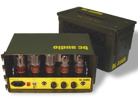
No blog is not complete without eye candy
 
.........PART 2 preview .........

In my next post, I'll spend time on the chassis.