Showing posts with label MachMate build. Show all posts

Saturday, April 3, 2010

ITS ALIVE!!!!!!

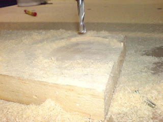
Virgin cut were commenced on 5:30pm 31st March 2010....

There outcome.......... Speechless....

I'll just let the pix talk...


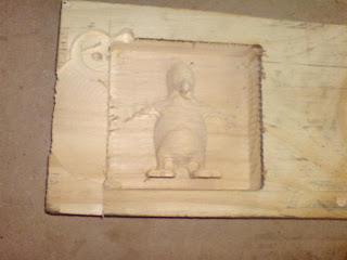
The 1st complete relief carving....
Will frame this as it is for me to show my grand children...

Now that I'd build the "car" I'll have to learn to drive.

Friday, March 19, 2010

Z-Axis Concoction

You might notice there isn't much mentioned on the Z-axis.

I did my own "design" to cure my needs to have my own signature in this machine.

Using Linear Slide & Rail bar is more expensive, but it does give peace to my mind & fulfill my over-sized ego...


There you have it.
All Axis are assemble (almost)...
The last piece of purchase to get this to machine to work will be the Gas Spring & a 500mm long gear rack.

Saturday, March 13, 2010

After the rail alignment, progress took a nose dive to near stop. The are 2 reasons (excuses to be exact) I can come out with.
1) I'm near physically exhausted & mentally fatigue from this build, its like taking up 2 extra jobs... and
2) After all that adrenaline rush from the previous tasks such as steel fabrications, rails grinding, alignments...etc really tough nut I'd cracked, the later jobs looked & feel so easy now, so much so that procrastination starts to creep in quietly...
Anyway, looking at the time & dough I'd invested in this baby, I made an effort to muster enough will power to continue with the journey before I add it to my dreadfully long "perpetually unfinished" project list.

Installed the gear rack on the rail.

Made the Y-track hold-down


 The Stepper Motor Drive Assembly


And here we have it. Competed Mechanical bits for the X & Y axis.

All that is left are the Z-axis before I proceed with wiring up the controls.

Saturday, March 6, 2010

Alignment

Now that the Chinese New Year celebration is over, & the main machine structure is up. It is time to proceed with the critical rail alignment work.

This is the most dreaded part of the build. Why so? We all know that we can ride smoothly on a bumpy & winding  road. It is the same with machine. without a through rail the machine can never travel straight & smoothly.

What is the primary objective ?
1) line the rail as straight as possible. Here, I set out for within 0.1mm which is equivalent of +/-50micron. which is about the diameter of my hair (which I had just measured...)
2) straightness of within 0.2mm along the 4.4m length x-rail & 1.73m y rail
3) parallelism between the 2 x-rail of 0.2mm

Secondary objective?
1) Using the most primitive tools & equipment I can lay my hands on in my tool box.
Tools I used
1) Filler gauge with 0.05mm to 1mm
2) 30 lb fishing line
3) Aluminium shim salvaged from Coke can.
4) Hole punch
5) a few clamps
6) an aviation straight cut snipplet
7) some spanner
8) a 3lb hammer

No rullers, no micrometer, no dial gauge, no vanier calipers...

Can this be done? Oh Yes.
The last time I lay my hands on similar work was like 2 decades ago, after which I get to supervise/instruct others just by pointing my fingers + a bit of shouting when it calls for ;) . While they slough it out in tropical heat, I get to take refuge in nice air-conditioned office sipping coffee. The for another few year, I don't even get close to job like these...

It was tough at the beginning when I got rusty over the years, but like riding a bicycle, everything came back after a little fiddling.

Will post more on details... once I get everything organized...
Sunday, February 7, 2010

MechMate Gantry & Y-Car Assembly

With the availability of CNC laser cut machine, fabricator's life gets a lot easier then it use to be. BUT that doesn't say one gets a free ride when fitting them accurately.`

Level & alignment is of paramount important in this excercise. 
Hence, I build 2 adjustable trestle from C-Channel off cuts.drill & tap M12 holes for attaching adjustable leveler legs.


Setting up the box section beam on  the trestle.
  • Using Spirit level to line them on horizontal plane. 
  • Align the box section beam by measuring the parallel distance. Comparing diagonal distance to ensure they are square to each other.
  • Clamp down to hold the position.
Rubber mallet for fine movement by tapping them lightly on the correct places without damaging the paint work. 

.

When you are ready, spot weld to hold the assembly together & check for distortion.before doing the final welding.


Here are the Gantry & Y-car after welding & a coat of red oxide primer on the weld.

Closser view of the Y-car, The original paint was severy damaged by welding spatters....Shouldn't have painted...

.....Nothing I can't sort out with a coat of paint.

Friday, February 5, 2010

MechMate Table Assembly Works

From previous post, I shown the fabricated steel parts for the MechMate build in total loose form, all cut, dressed & painted. A friend who visited asked if they are kit supplied? Luckily, the scent of wet paint proved that I did the fabrication works.

This post will show the progress of assembling the "kit".

BTW, the table is good for 1220mm x 2800mm (8'x 12.5') working area.


The welding set


The "precision" measurement equipment I need for aligning the assembly.


Some of the welding were done on this make-shift welding bench. :)


The tube truss fitted & welded


How I fit the leg perfectly square & perpendicular to the main channel rail.


Both side frames completed


Aligned the two complete side frames square & parallel to each other


Place the table cross bearer on its appropriate position accurately. Then weld...


Fit & weld the cross pipe & diagonal pipe brace & you have a table.


There you have it, what is left is to get a group of 6 full muscle grown-up to flip this chunk of metal over...

This is only the table, we have gantry, Y-car....

Stay tune ;)

PS,
Is there anyone out there???? Give me a sign...
please do leave your comment & response in the comment lines...