
Tuesday, December 14, 2010
Sunday, October 31, 2010
What can my CNC do
Too many times I was asked what my machine can do...
AND... my usual reply
"It can do many things...."
"Cut, carve, engrave, mill, machining anything that is wooden, plastic or soft metal..."
"Only limit by your imaginations..."
These replies just won't satisfy anyone...
So I actually summon enough energy to break out of procrastination to write down a list...
Here goes...
Sign making – wood, plastic, foam, vinyl, and electronic LED signs.
CNC wood projects – pictures, carving, engraving, parts.
Cool projects – science projects, school projects, DIY projects, and club projects.
PCB milling, PCB engraving or PCB routing of circuit boards. PCB drilling and PCB testing.
CNC robot and robotics projects.
Arts and crafts, cut vinyl, paper, wood, plastic, 3D carving and engraving.
Invent – build prototypes for inventing and experimenting.
Education – robotic manufacturing, CNC routing, CNC machining, science models, physics projects, machines, electronics, woodworking, CAD, CAM. (Great for schools.)
Electronics projects – circuit boards, make enclosures, boxes, cases, labels, panels, and parts.
Mechatronics – Electro – mechanical parts.
Mold making for castings
Fiberglass mould
Lithopen
Scroll saw projects – makes parts faster and more accurate.
Homemade gifts and other projects.
Hobby CNC projects of all types, RC projects, and model making.
Robotics projects – build parts or complete machines.
CNC precision parts for demonstrations.
Pattern making, template making, inlays, and on lays.
Rubber stamps.
Loudspeaker cabinet
HIFI chassis, furniture
Acoustic wave penal
Wood clocks.
Wood furniture.
Cabinet making.
Door making.
Digital cutting for soft metals.
Boat building.
Plastic fabrication.
Rapid prototyping.
Arggg.... too tired to continue...
Tuesday, September 28, 2010
How to Tell Me What You Wanna Cut
CNC Cutting Service is new to local customer. In almost all cases, guiding the customers to provide information to fulfil his/her needs is a must.
Obviously, saying "YOU DESIGN, I CUT" is not even close to enough information...
Similarly, "I want a cabinet", "I want a chassis", "I want a box" are not specific enough too...
In this article, I will go through what I find helpful to a meaningful transaction.
These tips may seem pretty basic but they can save you time, and money.
This example shows material, holes numbers with detail, and a couple of dimensions.

We grouped the different thicknesses of MDF in to boxes.
The 12mm MDF (bottom left) was used a templates for the veneer.
The narrow strips are templates for the Hardwood edging. (top centre 25mm box)
25mm parts are machined upside down with work top key hole cut outs.
This may seem a bit chaotic

I sincerely hope that the above information is helpful to you like they are useful to me.
Any comments are welcome. Please feel free to comment. Need your comment to horn my communication skill.
Pleas Please Please!
Ciao
Obviously, saying "YOU DESIGN, I CUT" is not even close to enough information...
Similarly, "I want a cabinet", "I want a chassis", "I want a box" are not specific enough too...
In this article, I will go through what I find helpful to a meaningful transaction.
All I really need is a clear idea of what you are after.
These tips may seem pretty basic but they can save you time, and money.
- Send something in writing: Email, or Letter is fine, or just Email an image.
- Don't spend to much time on plans to start with, a quick sketch or photo of what you are really after plus if needed a chat on the phone will cover most thing.
- It's better to get a rough sketch to us sooner than a fine drawing later.
- If you want simple shapes like circles, rectangles, triangles or quadrants, a simple list with radius or diameter and the thickness plus quantities.
- In a perfect world we like longer lists on an excel sheet with each dimension in a separate cell. If you don't know what I'm on about ignore this.
- prefer sizes in millimeters but if you happier with inches or centimeters please state which. We just need to understand what you want.
- If you can send a CAD drawings or vectored files please do.
- If possible put all parts, and instructions on a single file.
- If your not a CAD person don't worry we can still read Bits of paper, Word Doc's, PDF's, JPGS, Spreadsheets, etc.
Tips to sending CAD files for CNC routing machining
- Importing from Apple Mac vectorworks can still cause problems but it is very rare
- It's always a good idea to also send a PDF file so we can check against the CAD file, which can sometimes be corrupted when converting to our CAD/CAM software.
- Intersecting curves, and lines need to connect.
- Lines on top of each other can cause problems.
- We can sort these things out but if their are a lot of curves or shapes it can be very time consuming.
- Scale should be 1 - 1 full size. Not vital but a good idea.
- We machine from files in millimetres so millimetres are preferred.
- Polylines with thicknesses should be set to thickness zero.
2D Files
- All the parts on a single of CAD file grouped in material, and thicknesses.
- If we have 20 or 30 individual files to handle it's harder to get an over view for quoting, and key file can be missed.
- Notes, and details on the file are very useful. Files can be loaded on different computers stations, and emails, and note become separated.
- Using layers for groove depths board thicknesses different hole sizes an be very useful.
- Early version of DXF, and DWG are can be more reliable than the latest version.
- When we transfer data via DXF we will use version 13 or 2000 if possible.
- We find DWG slightly more stable than DXF.
- If you have a 3D model it is always useful for getting an over view.
- It can take time to convert a 3D file into a 2D file so send the 2D file as well.
3D Files
- We Machine with V-Carve Pro & AutoCad for preparation
- We can take most 3D Solid and Surface files.
- Mesh files like STL can loose definition when the parts are large.
- An indication of the block size is always useful.
Tips for Adobe Illistrator users sending files for CNC Routing.
- If you can send the file as PDF as well it can be a great help.
- Files can sometimes change when tranfered to other programs. PDF's give us a visual double check.
- It's a good idea to put scale reference like a 500mm square with a dimension on the file with free flowing shapes. Some time's the scale will change when changing from Illustrator to CAD.
- We can import Adode Illustrator so machining directly from your files is possible.
- If you want text machined explode the fonts to turn them in to graphics. If you send text as fonts, and we don't have your font a different one will be substituted, and your elegant font can come out as Helvetica. Again a PDF can give us a quick double check.
- Send the your file as an Adobe Illustrator file not as a DXF.
Examples of files for CNC routing
- We like all the information on a single file.
- Some times the file becomes separated from the Email.
- From starting to writing the CNC machining program takes just a few minutes.
- This saves time, helps prevent error's, and keeps setup cost to a minimum.
This example shows material, holes numbers with detail, and a couple of dimensions.
This job was more complex but the principle is the same.
CAD drawing of parts for a 10 metre boardroom tableWe grouped the different thicknesses of MDF in to boxes.
The 12mm MDF (bottom left) was used a templates for the veneer.
The narrow strips are templates for the Hardwood edging. (top centre 25mm box)
25mm parts are machined upside down with work top key hole cut outs.
This may seem a bit chaotic
I sincerely hope that the above information is helpful to you like they are useful to me.
Any comments are welcome. Please feel free to comment. Need your comment to horn my communication skill.
Pleas Please Please!
Ciao
Friday, September 24, 2010
How to Vectorised Artwork from Photo & Scanned Images
CNC work with vector files, eg. file extension such as .svg, .dxf, .dwg, stl, ai....etc etc
Normal digital photo or scanned images are in raster format, eg. file extension such as .jpg, .png, .bmp
There is an easy way to do it using free open source Graphic Editing software call InkScape.
I wanted to produce a video tutorial but I quickly realised there are plenty smarter people with sexier voice & production skill... hence this wonderful video tutorial...
The first 7min 30secs is what I use exactly for my CNC work... Then save the result in .svg or export as .pdf.
*ps, some times, "edge Detection" yield a better result... but there are no fix solution, its really all about trial & error.
#
#
#
This is for color pix
So now you know how to capture vector graphics using Digital camera, Scanner & robbing pix from the net...
Tuesday, September 21, 2010
Put em Togetter
This is one of the easiest combination of joinery I use.

My vocab is not good enough to describe
Hopefully the pix can say it better.

Do you get it?


My vocab is not good enough to describe

Hopefully the pix can say it better.

Do you get it?

Digital Wood Joinery Lesson No.3
Finger join is another of my favourite. Practical & aesthetically pleasing to my eye.
Picture tells a thousand word... let the pix talk...

##PS,
I would love to post phot of this but I have yet figure out the way to make onject float in mid air...
Picture tells a thousand word... let the pix talk...

##PS,
I would love to post phot of this but I have yet figure out the way to make onject float in mid air...
Friday, September 17, 2010
Digital Wood Joinery Lesson No.2
The 3D illustration isn't as clear to some readers as I wish they are so here is a 2D figure with a few more varieties of tong & grooves which I like to employ in my designs.
 The Magenta vertical blocks are the various varieties of Tong (male) & the bottom horizontal Cyan are the Grooves (female).
the 1st & 2nd on the left is the simplest form which are my favourite.
the the 3rd requires turning the job to cut both sides of the tong hence I rarely use it.
The 4th, 5th & 6th are great when I want to show off how my stuff snaps on perfectly... :D
The grooves are usually half the wood thickness & the narrower tong of the 5th, 6th & 7th are normally half the plank thickness too.
With CNC precision & cut quality, I usually design the tong to fit the grooves exactly, no need for small clearance/allowance for adjustment during assembly like traditional carpenters do.
These Tong & Groove Joints are self-reference, holding themself up when assembled & you don't need set sqare to square them up or clamps to hold them on. A few tander knock will persuase them to mate up nicely.
Wednesday, September 15, 2010
Digital Wood Joinery Lesson No.1
Wood joinery is a priced craft.
Traditionally, any carpenter will feel insulted if you say he nail up his work...
Deep inside, I too feel humiliated without implementing some sort of wood joints in my personal projects.
 The RED & Blue are simple butt joints... I don't feel proud when I use them....
The Magenta & Cyan are tong & groove some call it tenon & mortise... this is the least I'll have in my personal projects.
Another modern woodworker's must have is PVA glue, commonly called wood glue or white glue. It is a water based glue that will not break before the wood fiber tears... great for indoor use.
A properly glued joint will take all the abuse you can throw at it before the wood itself give way...
SAY NO TO NAILS!
Traditionally, any carpenter will feel insulted if you say he nail up his work...
Deep inside, I too feel humiliated without implementing some sort of wood joints in my personal projects.

The Magenta & Cyan are tong & groove some call it tenon & mortise... this is the least I'll have in my personal projects.
Another modern woodworker's must have is PVA glue, commonly called wood glue or white glue. It is a water based glue that will not break before the wood fiber tears... great for indoor use.
A properly glued joint will take all the abuse you can throw at it before the wood itself give way...
SAY NO TO NAILS!
Thursday, September 9, 2010
CNC-ed Stools
Kenneth & Gabriel threaten to boycott me if they don't get a chair to seat on their next visit to my shop... :(
Buying chair for my shop use just isn't me... Too lazy to hand build some chairs... Procrastination sets in when it is a non-paying design job....
There must be plenty of free chair plans available in the net... so started strolling mindlessly across the WWW....
One will find when one seeks.
A nice stool design in the project page of 100kgarages. I like what I saw here and downloaded the free cad files immediately.
 Unfortunately, I can't cut it as it was designed for 3/4 in thick Plywood but I only has 18mm thk MDF. Some customisation is require... but hey, having a free download already save me from loosing gallons of brain juice... can't complain over that...
Without further a do, open up the CAD file, changed the slot & finger joint size to suit the 18mm thk MDF I have, It is always a goof practice to double check the actual thickness for both plywood & MDF before working with it as they can very as much as 3mm... A good a verneer caliper reads 17.4mm averageof 5 readings...
To prevent any possible infringment of trademark of the Makers & the Shopbot, I removeg their logo from the stool panels just in case & pop in some simple graphic pattern? The added bonus is reduction in weight :)
Then pop the modified CAD file into my CAM program, do some careful tool bit selection, tool feed rate, put in some tabs & G-code is ready for my Mighty Blue Beast.
Load up the MDF sheet, calibrate the positions, turn on the dust collector & I'm off for an extended coffee break.
The stool parts are completed & ready for assembly when I return...
As usual, everything snap-on perfectly.... ;)
 This should make Kenneth & Gabriel happy on their next visit ;)...
Buying chair for my shop use just isn't me... Too lazy to hand build some chairs... Procrastination sets in when it is a non-paying design job....
There must be plenty of free chair plans available in the net... so started strolling mindlessly across the WWW....
One will find when one seeks.
A nice stool design in the project page of 100kgarages. I like what I saw here and downloaded the free cad files immediately.

Without further a do, open up the CAD file, changed the slot & finger joint size to suit the 18mm thk MDF I have, It is always a goof practice to double check the actual thickness for both plywood & MDF before working with it as they can very as much as 3mm... A good a verneer caliper reads 17.4mm averageof 5 readings...
To prevent any possible infringment of trademark of the Makers & the Shopbot, I removeg their logo from the stool panels just in case & pop in some simple graphic pattern? The added bonus is reduction in weight :)
Then pop the modified CAD file into my CAM program, do some careful tool bit selection, tool feed rate, put in some tabs & G-code is ready for my Mighty Blue Beast.
Load up the MDF sheet, calibrate the positions, turn on the dust collector & I'm off for an extended coffee break.
The stool parts are completed & ready for assembly when I return...
As usual, everything snap-on perfectly.... ;)

Sunday, August 29, 2010
EMC2 Revisit
Had a go at the Mach3 trial version earlier, it is nice package packed with load of goodies but it does has a 500 lines limit, until I pay up US175 for the full version... It was a lot of money to me so I revamp my system to EMC2 the open source program that is free to own & most importantly free to tweak.
Presently, EMC2_2.4.3 release is available & it can run in the latest Ubuntu 10.04 LTS released which can handle dual-core mobo. BUT since my mobo is single core ATOM board & I'm to anxious to get my machine in full operation mode as soon as possible, I stick to the Live Disc which contains EMC2_2.3.4 + Ubuntu 8.04LTS. I'll go for 10.04 & EMC2_2.4.xx when they comes in live disc...
It is great to have EMC2 back in business, the motors sounded happier, smoother & refine.
From the jam packed Mach3 screen, the bare & simplistic EMC2 AXIS screen suddenly feels empty... AND I missed the Auto Z Touch-off feature... Without further a do, I dig into information on Auto Z Touch-off feature in the wide sea of WWW.
Nothing is new under the sun... apparently; Many EMC2 users had their own concoction & I found good information on one of the step-by-step how-to here...
http://wiki.linuxcnc.org/cgi-bin/emcinfo.pl?ClassicLadderExamples#Single_button_probe_touchoffand here is how this thingy came about.
http://www.cnczone.com/forums/showthread.php?t=62423
They involve pyPVC which is a screen editor to tweak the custom virtual panel & Classicladder which is a ladder program. on top of that one has to be well verse with the MDI_COMMANDS in the Axis HAL & some Python language....
Took over a week to have a creak at the programes without much success... hence, to save time & loosing hair, I put on my copycat hat & shamelessly copied every step to the teeth & after some debugging & troubleshooting, ITS ALIIIIVVVE!!!
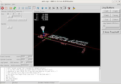
While I was at it, I squeeze in the jogging button for convenient operation.
Next will be a HID (Human Interface Device) using a common wireless game pad.... Don't wait up, I'll never know when I'll get there...
Saturday, August 21, 2010
Children Study Desk & Chair Set
Carving, Engraving & Profile Cutting is fun & the product are pleasant to the eye. BUT mostly useless... Very much like having sex...
This doesn't satisfy my natural crave to build something useful...
I've seen many furniture we made with CNC router... but can this really be done without any further human inteference?
It is unevitable that I set out to build a set of functional furniture... eventually... & that "eventually" came sooner then I could anticipated...
 The choice of the month is a Children Desk & Chair set. Why Children furniture you may ask... They are no less difficult then any other furniture & they are smaller (that means less material to buy...) period...
Took some serious effort into research of suitable joineries... After over 2 weeks of toying with various design combination in my head... I conjure enough energy to keep myself nailed infront of the computer monitor for 2 full days to come up with the 1st version...
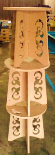
After a not-so-satisfied prototype & some alteration on the original version. This is my final results. A chair that is ergonimically correct, light-weight & assembled (easily) without glue straight out of the machine. AND (most importantly) they look right to my eye too...
"Flat-packe" profile cut


Now... How should I paint this thing...
This doesn't satisfy my natural crave to build something useful...
I've seen many furniture we made with CNC router... but can this really be done without any further human inteference?
It is unevitable that I set out to build a set of functional furniture... eventually... & that "eventually" came sooner then I could anticipated...
 The choice of the month is a Children Desk & Chair set. Why Children furniture you may ask... They are no less difficult then any other furniture & they are smaller (that means less material to buy...) period...
Took some serious effort into research of suitable joineries... After over 2 weeks of toying with various design combination in my head... I conjure enough energy to keep myself nailed infront of the computer monitor for 2 full days to come up with the 1st version...
After a not-so-satisfied prototype & some alteration on the original version. This is my final results. A chair that is ergonimically correct, light-weight & assembled (easily) without glue straight out of the machine. AND (most importantly) they look right to my eye too...
"Flat-packe" profile cut


Now... How should I paint this thing...
Tuesday, August 17, 2010
MACH3 endeavour
My Ubuntu OS based PC controller for my MechMate died...
After days of hair-pulling troubleshooting hours, the culprit was found to be the fried Thumb Drive I used as the main storage media... Now, that was a surprise... how often you hear of fried USB thumb drives...
The opportunity of an alternative motion control software arises.
From what I learnt, EMC2 & MACH3 are the two dominant controller software used in the CNC hobbyist community. Both has strong & huge community based support forums & free to download user developed plug-ins.
I took on EMC2 in the first place because it is a free software, not just it doesn't cost real money to own, it is also free from constrain when use.
Thanks to a donated Dell P4 machine with a licensed Window 2000, 1.6Ghz, 512Mb Ram, 20GB. & most importantly a LPT port.
I seize the opportunity & downloaded the Mac3 Trial version for the job.
This trial version is as much as the paid version (USD 175..) the only limitations are that it can take up to 500 command lines... & they limit the pulse rate to 25kHz. Still it is enough for trial cut with simple design but insufficient for complex engraving & carving works.
Setting up is a breeze with my prior experience with EMC2 under my belt.
I immediately rig up the much talked about Auto-Zero programme and scavenged a piece of blank PCB from my junk pile as the touch plate, soldered a thick gauge wire to it & connected to the free I/O ports on the breakout board. Down loaded the plug-in & again, everything worked seamlessly. It was a breeze, even monkeys can do it!
I the tried my luck with the Joystick HID setup, but unfortunately, the plug-in don't work in Win2K... #@!$@#~$!
There are lots of handy feature cramped into this package, it can generate G-code for table surfacing, Pocketing, Spiral cutting, Thread cutting... etc etc etc.. Many handy controls were on the screen & the screen is programmable... Learning curve isn't that steep too.
The down side is that the screen is really cramped with many feature that are not required...
My verdict?
If this is the first time for you with this PC based Motion Controlling Thingy... stick to MACH3...Everything you need for a beginner are there! Even those that you don't need... Its a no-brain-er... It even comes with a CAM programme call LazyCam...
BUT if you want more freedom over the program functionality, go for the EMC2 where the screen is Spartan & the user need to custom their own any additional features such as Auto Zero, Auto-Homing... etc which are also available for free download...
For now, (USD175 is still a lot of money for me...) I will spend more play time with this Mach3 Trial program & when I decided to switch back to EMC2, I'll teach my EMC2 all the neat tricks in Mach3...
Thursday, August 12, 2010
Another Health Hazard Management - Dust Collector
Anyone whom ever worked with wood working power tools can tell you how fast & convinient they make, BUT no one ever mentioned the mess it left with the amount of wood dust, saw dust they generate...
Wood dust get into everywhere! That includes every possible crackes, gap, opening in the building... Those which manage to get air bourn will stay air bourne for hours!!!
Not forgetting the demage they can do to our lungs, nostril & any other opening in your body...
I'm a lazy sob, I hate to do cleaning chore... & I don't want to die of lung cancer...
Naturally, I'm reluctant to use my CNC Router....Cleaning the mess is hell!!!
To keep my sanity & healthy lungs, I installed a full fledge 2-Stage Dust Collecting System... which really is nothing more then a glorified industrial grade vacuum cleaner...
 I bought this Twin-Bag Single-Stage Dust Collector, I did planned to build this from scratch but again... As I'm a lazy sob especially when the financial benifit did not churn out more the 70% savin...
The white thingy is the fabric filter bag which stop fine dust from entering the shop ambient.

This is the centrifugal fan which acts as the "sucker"
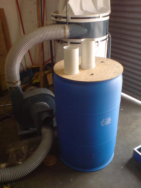
Since the fan impellar & filter bag do worth some money, it will be best to have a buffer to remove most of the saw dust & foreign object from getting to them. The ideal solution (for me) will be a dust cyclone, which is not difficult & expensive to construct but I came accrose this Thien Separator in the internet which is even easier & cheaper to construct.
 This is the Thien Separator which were constructed from a 200L barrael which I robbed from a friend & some fitting & CNC cut plywood. This will drop off 80~90% of the saw dust & any heavy foreign object from contact with the fan impeller and fill up the filter bag.
 This how they look inside.

Another view of the separator internal organs
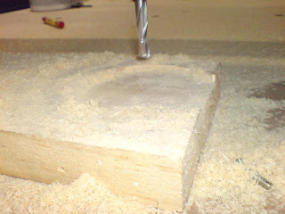
it will confirn the saw dust within the effective vacuum suction region. Also capture larger wood chips from flying all over the place. the brush is a door seal brush & the rest of the wooden structure were cut by my CNC router. Everything just snapped on seamlessly.
The original hole around the cutting bit is round but was accidently demaged during test... but it still work beautifully as it is now... (too lazy to make another...)
Now.... I am fresh out of excuse to delay cleaning up the workshop....
Wood dust get into everywhere! That includes every possible crackes, gap, opening in the building... Those which manage to get air bourn will stay air bourne for hours!!!
Not forgetting the demage they can do to our lungs, nostril & any other opening in your body...
I'm a lazy sob, I hate to do cleaning chore... & I don't want to die of lung cancer...
Naturally, I'm reluctant to use my CNC Router....Cleaning the mess is hell!!!
To keep my sanity & healthy lungs, I installed a full fledge 2-Stage Dust Collecting System... which really is nothing more then a glorified industrial grade vacuum cleaner...

The white thingy is the fabric filter bag which stop fine dust from entering the shop ambient.

This is the centrifugal fan which acts as the "sucker"
Since the fan impellar & filter bag do worth some money, it will be best to have a buffer to remove most of the saw dust & foreign object from getting to them. The ideal solution (for me) will be a dust cyclone, which is not difficult & expensive to construct but I came accrose this Thien Separator in the internet which is even easier & cheaper to construct.


Another view of the separator internal organs
it will confirn the saw dust within the effective vacuum suction region. Also capture larger wood chips from flying all over the place. the brush is a door seal brush & the rest of the wooden structure were cut by my CNC router. Everything just snapped on seamlessly.

The original hole around the cutting bit is round but was accidently demaged during test... but it still work beautifully as it is now... (too lazy to make another...)
 suction hose attachement.
 Then the flexible host.
Now.... I am fresh out of excuse to delay cleaning up the workshop....
Sunday, July 18, 2010
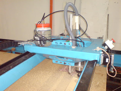
Upgrade Cooling water System for Water Cool Spindle
My spindle cooling water pump gave up on me!
No, I didn't fry my spindle along with it :)
I was so glad I had the reservoir made out of transparent plastic container! Saw that the water flow was reduced to a trickle when I started up the pump 2 weeks ago...
After some leg work, found a nice submersible pump. It was a love at 1st sight! black aluminium body, stainless steel impeller & shaft, 415V/3 phase, 1/10 horse power (75 watt) , capable of 2m head but didn't indicate the flow rate... & the best part was its has a RM250 price-tag! well within my RM300 budget! I love it so much that I couldn't care less about the flow rate...
I only need 350 ml/min which I recon a lovely pump of this specs will surely achieve.
Another pleasant surprise to find the shop next door carry some heavy-duty PE tanks! So I just got hold of a 16 liter tank, I choose it as it look about right size to keep the pump stable...
More leg work to find some extra 6mm tubing, connector, reducer, 4 core wires, an on-off switch, some screws, washers, pp tubing tape...
 Took a nice Sunday morning in cooling rain to tie everything up nicely...
Open up all the necessary opening for mounting the pump, fit the reducer at the outlet,use up some 20m of 6mm pneumatic tubing to go along the cable chain, I like the pneumatic tubing as it has stiff tube wall, it is light weight & the glossy finishing eye-catching... & some fittings to go along...
Tie up the electic cable, switch, got the motor direction correct & ready for a test.
The pump fills up a 1 liter paint can in 2 minutes 45 seconds, so a healthy 363 ml/min. consider the amount of work it has to get through some 30m long tiny 6mm tubing... an improvement over my old aquarium which was 300 ml/min at its best...
Ran the motor with the spindle running for over an hour & everything is cool & nice! This industrial grade outfit will serve me trouble-free for a long time...
Total damage? RM276... yeah... don't believe everything written on the price tag.... LOL
I would conclude this upgrade a complete success!
What next?
I can' really see the water level despite the translucent tank wall, will buy some of car radiator coolant to give a distinct color to it & give better corrosion protection to my pricy spindle. If it still doesn't work, I'll die the coolant with ink :)
Friday, July 9, 2010
CNC Hobbyist Club
I love to meet new faces, make new friend. Made more than a few friend around the world through participating forums of various kinds.
Since I started this blog, I received a few mails showing interest in CNC hobbyist activity. Hence, inspired the idea of forming a local CNC Hobbyist Group as a platform for like interest individuals to get together over Teh Tarik session, maybe set up a forum, a Facebook Group or something...
Curious to know how many might be interested... & see if the number warrant any action...
You can respond through the posting comment here
or
email to me Tinkeringken at Gmail dot com
Any comment & suggestion are welcome.
Thursday, June 10, 2010
Building Amp - the battle plan
It is always best to plan ahead. No exception in amp building project.
The first thing I look into is the chassis. Chassis can make or break the project.
Dimensions
My choice is, 17in (432mm) wide, 12in (305mm) deep & 4in (100mm) height.
17 inch wide is the commonly accepted "full width" of any Audio/Video home equipment.
12 inches deep is the size I experienced as "just big enough" physically yet not too clumsy visually.
4 inches is the height that is "just-tall-enough" to mount most audio components such as power capacitors & chokes; This I learn through years of experience.
Layout
I like to keep the power transformers to a corner of their own to keep potential electromagnetism headache which it is associated with. In this particular build, the power trans I am using is a bare, its ugly & exposed, no covers or bells, so I for safety & aesthetic reasons, will keep them out of sight by mounting it inside the chassis. is ugly...
Took some time to create a 3D model of my intended chassis, its only partly completed but these which are drawn will be final. Eagle eye readers will notice I have a larger bottom board for mounting the transformer. This is important, transformer is a chunk of metal & it's really heavy... So a strong base is important. Too lazy to put in all the components in the 3D model. I draw a 2D layout instead.

The first thing I look into is the chassis. Chassis can make or break the project.

Dimensions
My choice is, 17in (432mm) wide, 12in (305mm) deep & 4in (100mm) height.
17 inch wide is the commonly accepted "full width" of any Audio/Video home equipment.
12 inches deep is the size I experienced as "just big enough" physically yet not too clumsy visually.
4 inches is the height that is "just-tall-enough" to mount most audio components such as power capacitors & chokes; This I learn through years of experience.
Layout
I like to keep the power transformers to a corner of their own to keep potential electromagnetism headache which it is associated with. In this particular build, the power trans I am using is a bare, its ugly & exposed, no covers or bells, so I for safety & aesthetic reasons, will keep them out of sight by mounting it inside the chassis. is ugly...
Took some time to create a 3D model of my intended chassis, its only partly completed but these which are drawn will be final. Eagle eye readers will notice I have a larger bottom board for mounting the transformer. This is important, transformer is a chunk of metal & it's really heavy... So a strong base is important. Too lazy to put in all the components in the 3D model. I draw a 2D layout instead.

Thursday, June 3, 2010
Building Valve Amplifiers
This is a series of article on the actual work & design consideration when I build valve amplifier.
 Tube amplifier is an electronic equipment, so it is natural to neglect the need for the mechanical works involved... you can't get anywhere without planing the mechanical layout of a valve amplifier.

The mechanical works involved are mostly in the chassis.


How about aesthetic appeal?
This is too subjective a subject to discuss, in my humble opinion, If the chassis layout is superb, it will always look good. but one thing for sure, a poor layout always looks ugly.

Chassis Layout
There is enough stuff to write a book on this topic alone but I won't torture the readers with my lousy writing skill... Instead, a summarised criteria.


The mechanical works involved are mostly in the chassis.
How about aesthetic appeal?
This is too subjective a subject to discuss, in my humble opinion, If the chassis layout is superb, it will always look good. but one thing for sure, a poor layout always looks ugly.
Chassis Layout
There is enough stuff to write a book on this topic alone but I won't torture the readers with my lousy writing skill... Instead, a summarised criteria.
- Rigid Chassis to take the weight of the irons & owner abuse.
- Electromagnetic induction, Components must be positioned/spaced correctly in relative to each other to minimise electromagnetic induction, mostly concern the placement of transformer, chokes & valves.
- The connecting wires between each components should be as short as possible to minimise chances of hum induce into the signal & excessive voltage drop.
- All components must be mounted securely & rigidly as all components are microphonic to some degree, hence any vibration will affect the final acoustical result.
- Provide sufficient ventilation to minimise heat build up.
Tuesday, May 25, 2010
Learning Aid
Many interested parties approached me with their dream to enlist my CNC service to cut/carve their dream project. The encounter will start with a warm welcoming introduction, all the usual chatter, asking what I can do & bla, bla, bla... all were rosy & cheesy until I ask what exactly they want me to cut.... Most describe their requirements verbally with a lot of confident,
here is a typical example,
"It a circle this big (size it up with his hand), with a section that is curved like this (swivel his hand in a wave form in the air), has a contour to fit this very rare fitting (show me a photo of the fitting) that goes in this bit deep (sign with his thumb & index fingers). There carve some flame over here (again waving his hand in the air). How soon can I have it?"
Me : " Do you have a drawing?"
" No."
" A copy of the fitting?"
" No."
" Do you have the dimension of the circle, the curve, the fitting and the depth, type of material?"
" No, I tot you can do circles, curves & accurate depth? and please don't make me mortgage my house..."
".............."
Not wanting to be negative about this but its really not enough info for me to do anything at all...
I mostly end up encouraging them to do their own drawing to save the drawing & design fee that I will eventually charge them.
As I require vector graphics, it is natural that I narrow my learning towards that...
AutoCad is my personal preference, and INKSCAPE is free...
IMHO, This is the only place you need to be to learn up everthing there is to know about AutoCAD for free.
If Autocad is too expensive or too intimidating, you can use a vector graphic editing package call InkScape, its Open Source A.K.A Free. Free download here
Some good tutorials & instructions Here
Many videos in YouTube on InkScape
This gives an excellent introduction to InkScape
This has all the tutorials that you may need to become a pro.
Hope this helps.
Monday, May 24, 2010
How Boring is Drawing

You can not get too bored with drawing...
Just visualise this, when we scribble on a piece of paper, the years of foundation training of flying the crayon on the wall during our childhood days kicks in subconsciously & we are free to draw any lines on the piece of paper & hopefully these lines will mean something to anyone other than ourselves...
When we wish to draw stright lines & constructing meaningful shapes on a piece of paper, the hands will grab a ruler or a protractor & our secondary training during primary & secondary school takes over & there we have nice orderly lines on a piece of paper which actually mean something to most people...
For those who took up some form of institutional engineering training or education will learn to draw & read engineering drawings properly & again subconsciously pack in the necessary information onto the piece of papers with lines which we call engineering drawings...
In my early stage of drawing with CAD, life was really frustrating... A simple task of drawing a straight line can turn into disaster... it really happened! I deleted an entire file because I click on something accidently.... dividing a line into a few equal section can take more than half an hour until I learnt that there is a command that I can use to do so with a few clicks on the mouse & all can be accomplished within a second... to draw a line on tangent of 2 circles turn into a full-blown construction drawings taking nearly an hours when a simple typing tan on the keyboard then right-click the circle can do the job...
Once you get more "fluent" conversing in the correct "language", things can get really interesting & fun filling... eg, we can use "offset" command to construct lines & check size of your design on drawing, make complex contours using "polylines" & play with its sub-commands such as L (for Line) & A ( for arc) on the keyboard, then drag the line to accommodate your desired shapes... copying object is a god sent when identical object are needed; Rotating parts in the drawing takes a bit of practice but they are extremely precise; Moving object to desired location/position is a breeze; Resize the drawing can save hundreds of hours of drawing; drawing chamber & fillers are just 2 clicks away;
Best of all, you can redo the drawing till the cow comes home & nothing is loss... I still recall the amount of eraser scrap covered desk after a drawing session during my school days... not forgetting drawings with holes made by excessive erasing with a laser knife on PP paper...
Wednesday, May 19, 2010
Pre-raquisite Software Skill for operating the BEAST
Building the CNC Router was a stressful but fulfilling experience. Inflated ego was the direct product of this memorable journey. BUT that is only the starting line of my CNC endeavour. Now that I have a machine at my disposal, I need to learn up how to drive this machine to churn out those beautiful artifact like we seen in the net.
In retrospect, running the machine is easy, but that is only after you actually operate the machine...
I totally over estimated my learning capacity, & underestimated the complexity of the software involvement in running a CNC machine. After over a month of tinkering with running the machine & many software packages, I come to this overly generalised summery.
You need a Drawing to convert to G-code, feed the G-code to the Motion Controller. To cut properly, one need to know the cutting tool characteristics, material properties & some machining procedure knowledge.
Drawings
To make something with or without CNC machines, we need to provide specific specifications of what to do, so coming up with a drawing is the first step.
From my understanding, we can use 2 types of drawing files, namely Raster & Vector.
In raster, examples are bitmap such as jpg, png etc. With this, the cutter will transverse the whole area covered by the file, this is how most 3D cutting is done. With Vector file, the cutter only travels along the path where the cutting is required, saving lots of time. this is how profile cutting & 2.5D are done.
Drawing software
With different cutting strategies different software are used. In vector files, we direct the cutter in straight lines to cut the profile or contours, leaving the other space alone. In raster file, the cutter will transverse every mm of the file... example of raster files are bitmap. & the generally accepted vector file format is .DXF, other formats are SVG, AI, STL... etc etc
I'm fortunate enough to have worked with AutoCad in my junior career life & residue memory helps a lot when relearning. This is my preference for 2D & 3D rendering but there are others such as SolidWorks. You can also use CoralDraw, Win Paint, Adobe Inventor, SketchUp Pro,.... Open source CAD drawing are not quite up to the fee software but I find Blender is a promising, still crude but its getting somewhere.
I also learn that one doesn't need to draw a drawing from scratch everytime, especially when we are dealing with ornamental & art craft... We can "convert" raster files to vector files by tracing bitmap. I downloaded the open source INKSCAPE software which can do many capabilities of fee software such as the Coraldraw & Adobe AI.
G-code
One can write G-code from scratch if they feel they are up to it, BUT I'm too lazy for that... CAMBAM, UCANCAM, SHEETCAM, LAZYCAM... a whole library of CAM software which can translate vector file into G-code. I evenetually ended up with VCarve Pro for 2D & 2.5D works & Cut3D for 3D works..
At the end of the day, depending on requirement, all common or not so common software packages works, the difference are in the learning curve & the ingenuity of the user to utilise the available capabilities of each. Its a compromise of $, time & requirement.
Saturday, April 3, 2010
ITS ALIVE!!!!!!
Virgin cut were commenced on 5:30pm 31st March 2010....
There outcome.......... Speechless....
I'll just let the pix talk...


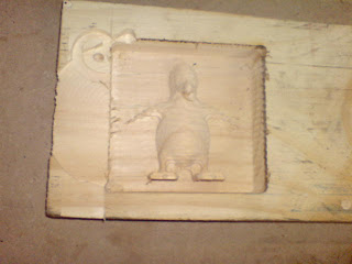
The 1st complete relief carving....
Will frame this as it is for me to show my grand children...
Now that I'd build the "car" I'll have to learn to drive.
There outcome.......... Speechless....
I'll just let the pix talk...


The 1st complete relief carving....
Will frame this as it is for me to show my grand children...
Now that I'd build the "car" I'll have to learn to drive.
Sunday, March 28, 2010
When is The Virgin Cut
In the beginning, I gave myself an ultimatum to make some wood dust by March 2010, & its only 3 days way...
Without further ado, here is the status.
 Installed the cable chain & layout most of the cables

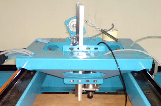
 A closer look at the Gantry
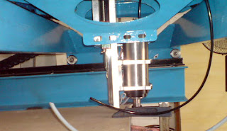 The spindle took position.

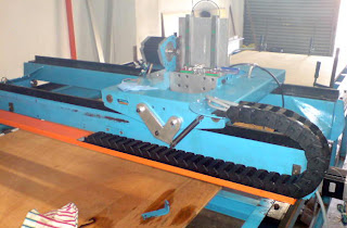
Spoil-board in place. now it really looks like a mean machine!
Well, getting closer now, hmm.... still need to commission the spindle, build the water cooling system for the spindle, mount the control panel, do the final cable connection, do the Emergency -Stop installation, install the gas spring, mount the Variable Speed Drive, ... and...... that's it... I guess....
My brother had booked the front seat & my neighbors are all enthusiastic to see the blue beast in action, time & money running low, potential customers & business partners asking for samples...... etc etc
...........lets see if I can make the virgin cut happen on 7.pm, Wednesday, 31st March 2010.
Anyone interested to witness this historical moment (at least it is to me ;) ) are most welcome, bring your own drinks if you wish. I would appreciate a bottle of champagne or 2 for the occasion.
Thats all for now, gotta work on double shift to make this happen...
Wish me luck!
Without further ado, here is the status.


Spoil-board in place. now it really looks like a mean machine!
Well, getting closer now, hmm.... still need to commission the spindle, build the water cooling system for the spindle, mount the control panel, do the final cable connection, do the Emergency -Stop installation, install the gas spring, mount the Variable Speed Drive, ... and...... that's it... I guess....
My brother had booked the front seat & my neighbors are all enthusiastic to see the blue beast in action, time & money running low, potential customers & business partners asking for samples...... etc etc
...........lets see if I can make the virgin cut happen on 7.pm, Wednesday, 31st March 2010.
Anyone interested to witness this historical moment (at least it is to me ;) ) are most welcome, bring your own drinks if you wish. I would appreciate a bottle of champagne or 2 for the occasion.
Thats all for now, gotta work on double shift to make this happen...
Wish me luck!
Friday, March 19, 2010
Z-Axis Concoction

I did my own "design" to cure my needs to have my own signature in this machine.
Using Linear Slide & Rail bar is more expensive, but it does give peace to my mind & fulfill my over-sized ego...


All Axis are assemble (almost)...
The last piece of purchase to get this to machine to work will be the Gas Spring & a 500mm long gear rack.
Subscribe to:
Posts (Atom)